Most conventional high-frequency vibrators used in ultrasonic applications like machining or welding processes generate the working power based on principles of piezoelectric or magneto-strictive effects (see Fig. 1 & Fig. 2). After entering the transducer, the time-varying electric input energy will then be transformed into solid-body vibration; however, the heat dissipated during energy transduction and the high-frequency electric input source has made them more complex of such transducers. Hence, in this work the use of pneumatic excitation was proposed as an alternative, which aimed to utilize the self-cooling property of gas and the availability of such phenomenon under constant air pressure.

Fig. 1 Common Langevin type piezoelectric transducers (courtesy of Tamura Corp.)

Fig. 2 Construction of magnetostrictive transducers
(courtesy of Blue Wave Ultrasonics)
(courtesy of Blue Wave Ultrasonics)
In this work an undesirable phenomenon in aerostatic bearing design called "pneumatic hammer" was utilized. This phenomenon results from the rapid compression-expansion of the air flow (see Fig. 3 below), especially when there's a large compensated pocket which makes the compression-expansion process more drastic, and hence generates unwanted vibration (see Fig. 4 below).


Though pneumatic instability can lead to detrimental damage to aerostatic bearings; on the contrary, it can be beneficial to serve as a vibrator. To trigger the claimed vibration, stability theory of cylindrical aerostatic thrust bearings proposed by Licht and Fuller was used to determine the valid combination of system parameters. Also, detailed CFD simulation was executed to search for geometric parameters leading to higher stiffness and hence higher vibratory frequency (see Fig. 5).

The design concept was composed of two aerostatic thrust bearings in the opposite configuration as shown in Fig. 6, with another driven spindle oscillating back and forth due to pneumatic instability. Since the system can be seen as two springs in parallel, the system stiffness can be greatly increased and so as the vibratory frequency.

To realize aerostatic bearings with sufficiently precise restrictor dimension, a split type design was adopted as shown in Fig. 7. Little semi-circle features can be done by conventional manufacturing processes like CNC machining or unconventional ones like EDM. Illustration of first prototype is shown in Fig. 8, including partially sectioned view, explosive view, dimension outline, and a photo of finished product.


After experimental verification of first prototype, performance of claimed pneumatic vibrator was then further improved by reducing actuation mass and using high-precision spacers cut out of steel strips with great flatness to maintain evenly distributed air film thickness (Fig. 9).

The device presented in this work was fabricated using standard machining techniques. Experiments had verified that, the newly developed device can be triggered with a startup air pressure of 0.2 bar, oscillating frequencies can also be up to several kHz under 1.0~7.0 bar, and a maximum energy efficiency of 65% can be achieved at 2.7 kHz.

Fig. 3 Radial pressure distribution of an aerostatic thrust bearing
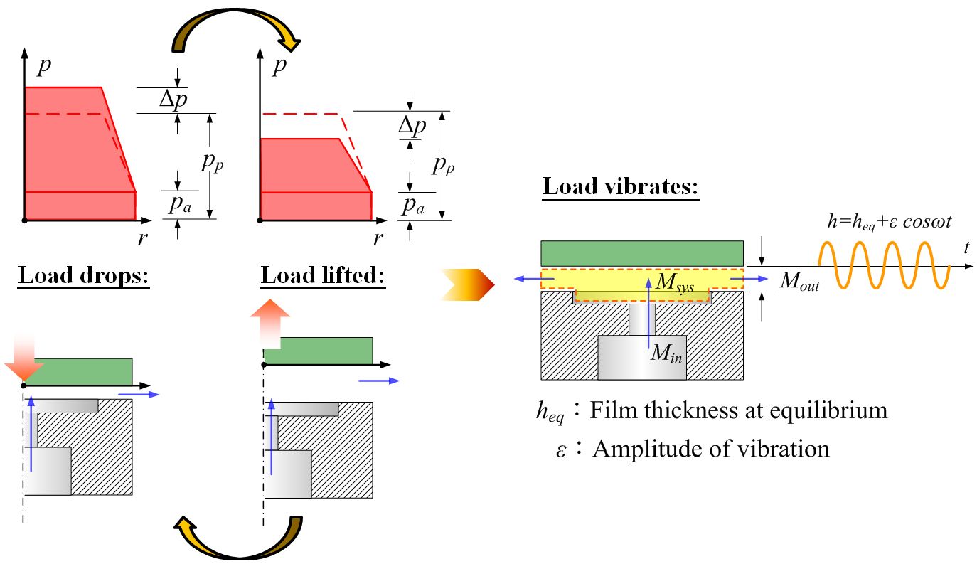
Fig. 4 Illustration of the undesirable vibration called "pneumatic hammer"
Though pneumatic instability can lead to detrimental damage to aerostatic bearings; on the contrary, it can be beneficial to serve as a vibrator. To trigger the claimed vibration, stability theory of cylindrical aerostatic thrust bearings proposed by Licht and Fuller was used to determine the valid combination of system parameters. Also, detailed CFD simulation was executed to search for geometric parameters leading to higher stiffness and hence higher vibratory frequency (see Fig. 5).

Fig. 5 CFD analysis of aerostatic thrust bearings
The design concept was composed of two aerostatic thrust bearings in the opposite configuration as shown in Fig. 6, with another driven spindle oscillating back and forth due to pneumatic instability. Since the system can be seen as two springs in parallel, the system stiffness can be greatly increased and so as the vibratory frequency.

Fig. 6 Design concept of the pneumatic vibrator
To realize aerostatic bearings with sufficiently precise restrictor dimension, a split type design was adopted as shown in Fig. 7. Little semi-circle features can be done by conventional manufacturing processes like CNC machining or unconventional ones like EDM. Illustration of first prototype is shown in Fig. 8, including partially sectioned view, explosive view, dimension outline, and a photo of finished product.

Fig. 7 Split type design of aerostatic thrust bearings

Fig. 8 First prototype illustration of claimed pneumatic vibrator
After experimental verification of first prototype, performance of claimed pneumatic vibrator was then further improved by reducing actuation mass and using high-precision spacers cut out of steel strips with great flatness to maintain evenly distributed air film thickness (Fig. 9).

Fig. 9 An improved design of claimed pneumatic vibrator
The device presented in this work was fabricated using standard machining techniques. Experiments had verified that, the newly developed device can be triggered with a startup air pressure of 0.2 bar, oscillating frequencies can also be up to several kHz under 1.0~7.0 bar, and a maximum energy efficiency of 65% can be achieved at 2.7 kHz.
No comments:
New comments are not allowed.